
Simple TVI Filter
Simple, Low-cost HF low Pass (TVI) Filter.
This circuit for a simple, low cost low-pass filter for HF was sent to me recently for QUA. The origin of the circuit is not exactly known, but is thought to be from Electronics Australia (if it was known as that then) of June 1977.
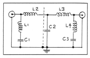
Figure 1. LP Filter.
L1, L4: 7 turns, 16swg spaced 5/8", 7/16" dia.
L2, L3: 9turns, 16swg, spaced 7/8", 7/16" dia.
C1, C3: 33pf
C2: 133pf (made of 100pf feed-thru + 33pf)
The circuit is self explanatory. There are several ways to construct the filter; the simplest is to mount all components on a piece of vero board or piece of pcb (using the hack-saw cut method to form mounting pads.
The filter needs to be mounted inside a metal box otherwise the harmonics you are trying to filter can possibly radiate out. Using a metal box also provides the basis for the best way of mounting the components particularly if a metal screen can be included in the centre of the box. The metal box can also be fabricated out of pcb soldered together. Although you will have to use some pieces of double-sided pcb to achieve closure of the box.
C2 is shown in the parts list as made up from a 100 pf feed-thru with a 33 pf in parallel. The feed-thru passes through the internal screen (see figure 2) giving the maximum isolation between input and output. An earth terminal on the box connected to the station RF earth is also good practice.
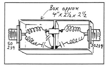
Figure 2. Suggested Construction of LP Filter.
Figure 2 shows a suggested construction of the Filter unit. The filter is bi-directional and it is not critical which side the 33 p f parallel capacitor is mounted.
I understand that the filter is good for normal (VK) power levels. If you can search out some good silver mica caps and use a transmitting style feed-thru you should have no troubles. Maybe some of the HF OTs might like to comment on this unit.