
2M Phased Colinear
2M Phased Colinear - Mar 1994
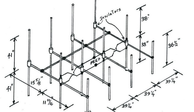
The 2meter phased colinear array depicted above is a design in much use down the South Coast (around the Milton-Ulladula Radio Club). It probably has its origins to a commercial design; however, many of these have been replicated in a wide range of styles and versions, all based on the design and dimensions shown above.
Your editor has seen versions made from aluminium tube, turned perspex insulators (in one case teflon) and almost commercial looking clamps and fittings resulting in an antenna bearing the qualities of a tailor-made, shop-bought unit, to the other end of the scale of others made from fencing wire and garden hose insulators.
The common factor in all these antennae is that they worked and worked well. Forward gain is better than 15 dB and front to back is very high; a function of the design itself. One version used a wire-mesh back plane instead of the individual reflector elements. The advantage of the design is that whatever polarity you want to use, you do not have to worry about the affect of the mounting and what is behind the reflector plane. You can bolt it on the side of a mast, the side of your house, caravan, car, tree or whatever.
A friend of mine who was residing at Jervis Bay about fifteen years ago had one of these mounted on the end of half a length of water pipe. He regularly was able to access Dural and had many other simplex contacts into the Sydney area.
Tuning the antenna is relatively simple. There is no adjustment to the element lengths and reasonable coverage of the 2 meter band can be achieved although VSWR will climb steeply at band edge. However, as it would be expected that the design would be used for either FM operation in the upper half or SSB in the lower half, you can expect an VSWR of well under 1.5:1 over a 2 MHz bandwidth. Matching to the feed is achieved by varying the phasing line spacing. Those that have built the antenna tell me that no real advantage is gained by using a balun at the feed point but, of course, the purists amongst us would naturally do this out of principle.
If there is sufficient member interest in this antenna, we could consider such a design as a Club project. It may be possible to prepare a kit; the bulk purchase of hardware could make this an economic proposition. Anybody interested, let me know and we'll see what can be done.
2M, 4 Bay, 20 Element Phased Array - Apr 1994
Well it had to happen. Just after printing QUA last month with the back page article on the 2 meter 4 bay, 20 element phased array along comes my March issue of RADCOM (the RSGB magazine) with a bigger (and better?) 5 bay, 30 el- ement array with a few more db gain. Essentially it is the same as the one described in last months QUA except that it has an additional director for
each bay and there is an additional bay.
The antenna described in the March RADCOM, believe it or not, was built by the article author (F50AU) for portable use, even though it is some 2.2 x .75 x 4 metres in size. What is very interesting about the RADCOM design is the method of construction which provides an ingenious, simple solution to the often difficult mechanics (plumbing) of building a large phased array of this type.
The method uses 25mm plastic conduit as both element insulators and element supports and is readily adaptable to the 4 bay antenna described in last month's QUA.
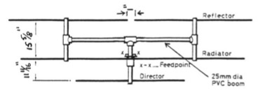
Fig 1 Conduit Support detail
Figure 1 (above) shows the dimensions of the conduit support (together with elements) for one bay. For a weather-resistant fixture, the elements can be secured in position using ex- poxy resin. The RADCOM article used a "chocblock" type electrical connector; however, this would be unsuitable for long term exposure due to dissimilar metal corrosion. The 25mm plastic con- duit can be reinforced with suitable metal pipe where the main boom attaches (using TV mast clamps) to give added strength at this point.
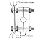
Fig 2 Showing detail of the Radiator/Phasing Line clamp
(mounted on FG PCB material disk)
Figure 2 (above) shows the method of connecting the radiator elements to the phasing lines. This uses a clamp made out of two pieces of aluminium square section with a holed drilled to accept the end of the radiator element. The two bolts that clamp this arrangement pass through the fibreglass pcb material disk and connect to the ends of the phasing lines. The lines are made from solid aluminium wire and the ends are flattened and drilled.
Figure 3 (below) gives more detail on this clamp and the connection o f the radiator and lines.
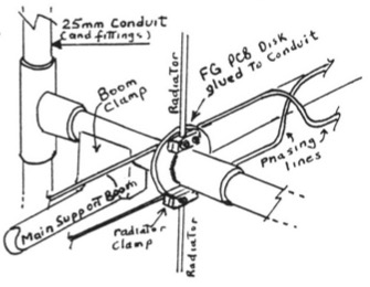
Fig 3 Detail of Radiator and Phasing line connection and clamping of conduit support to main boom
Also shown in figure 3 (above) is the attachment of (one of) the conduit supports (there are four of these) to a boom using TV mast type clamps. The boom has to be fairly substantial and could be suitable metal pipe. At least several inches spacing behind the phasing lines is required; this will be achieved if the "vertical" conduit support member is positioned midway between the reflector and radiator. Contact me if you want more information.